A CE 6.0 OS design template is a subset of the catalog components required to use Windows Embedded CE for a particular purpose. It is not necessary to start from a template when creating a new OS design, although it can save a significant amount of time to do so. It is straightforward to change catalog components later by selecting them in the Catalog Items View.
Choosing an appropriate template can save you development time and effort. For example, you might have to demonstrate the features of a new development board at a trade show. In this case, it is a good idea to start with the PDA Device or Consumer Media Device design template and add the required components and common Windows applications in the OS Design Wizard, such as the .NET Compact Framework 2.0, Internet Explorer®, and WordPad. On the other hand, if you are developing a driver for a Controller Area Network (CAN) controller, it might be better to start with the Small Footprint Device design template and only add what's absolutely necessary to minimize the size of the run-time image and to keep startup times at a minimum.
The OS Design Wizard is flexible and supports custom design templates. Template files are Extensible Markup Language (XML) documents, located in the %_WINCEROOT%PublicCEBaseCatalog folder. You can start with a copy of an existing Platform Builder Catalog XML (PBCXML) file and modify the PBCXML structures according to your specific needs. Platform Builder automatically enumeates all .pbcxml files in the Catalog folder when you start Visual Studio or refresh the Catalog Items View in Visual Studio.
OS Design Customization with Catalog Components
After completing the OS Design Wizard, it is straightforward to customize the OS design. The catalog is a repository for all the components that can be added to an OS design. It is accessible directly from within the integrated development environment (IDE). Click Catalog Items View in the Solution Explorer window pane. Almost every CE feature is divided into separate user-selectable catalog components, from ActiveSync to TCP/IP. You can select these components directly in the UI. Each catalog item is a reference to all the components necessary to build and integrate a feature into the run-time image.
When you add a catalog item that depends on other catalog items, you implicitly add these items as dependencies to the OS design as well. The Catalog Items View shows these items with a green square in the check box to indicate that they are part of the OS design due to existing dependencies. In contrast, the Catalog Items View shows manually selected items and items included based on a design template with a green check mark.
In the Catalog Items View, you can show all catalog components or enable a filter to display only selected catalog items. Click the downward arrow on the Filter button in the top left corner of the Catalog Items View in Solution Explorer to apply a filter or select the option All Catalog Items in the catalog to display the complete list of catalog items.
Provided that you know the name of the catalog item or the SYSGEN variable a component sets, you might find it more convenient and faster to search for the desired catalog item that you want to add or remove than to look for it manually. To search by item name or SYSGEN variable, type the search term into the text box at the top of the Catalog Items View and click the green arrow next to it.
To analyze the dependencies of a catalog item, you can right-click the item and select Show Dependencies to display the Catalog Item Dependencies window, as illustrated in Figure 1-1. For example, you can use this feature to see the reason for the inclusion of a specific catalog item as a dependency. In CE 6.0 R2, Platform Builder dynamically traverses the catalog to enumerate all components that depend on the selected item as well as all components that this item depends on.
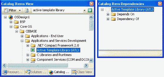
Figure 1-1 Catalog Items View with the search box and Catalog Item Dependencies window
Build Configuration Management
Windows Embedded CE supports multiple build configurations that you can modify separately. The two standard configurations are Release and Debug. These build configurations are automatically available when you create an OS design. In the Debug build configuration, the compiler generates debug information, maintains links to the source code in program database (.pdb) files, and, to facilitate debugging and step-by- step code execution, does not optimize the code. Windows Embedded CE run-time images compiled in Debug build configuration are generally 50 percent to 100 percent larger than images compiled by using the Release configuration. To choose a build configuration, open the Build menu in Visual Studio, click Configuration Manager, and then, in the Configuration Manager dialog box, select the desired build configuration under Active Solution Configuration. You can also select the desired build configuration by using the pull-down menu in the Standard toolbar.
OS Design Property Pages
For each build configuration, it is possible to configure a number of project properties, such as the locale, whether or not to include KITL, custom build actions, inclusion of subprojects in the binary image, and custom SYSGEN variables. To access these options, display the Property Pages dialog box by right-clicking the OS design node in Solution Explorer and selecting Properties. The OS design node is the first child object under the Solution top-level node. The caption corresponds to the project name, such as OSDesign1. If Solution Explorer is not visible, open the View menu and click Solution Explorer, and if Solution Explorer currently displays the Catalog Items View or the Class View, click the Solution Explorer tab to display the solution tree.
In the top left corner of the Property Pages dialog box, you can find a list box to select the build configuration. Among other options, you can select All Configurations or Multiple Configurations. These options are useful if you want to set properties for multiple build configurations at the same time.
Locale Options
In the Property Pages dialog box, under Configuration Properties, you can find the Locale node, which enables you to configure language settings for the Windows Embedded CE image, as illustrated in Figure 1-2. For most languages, the Locale property page covers all requirements to localize the OS design, but some languages, particularly East Asian languages such as Japanese, require additional catalog components. It is also important to note that some catalog components related to internationalization significantly increase the size of the run-time image.
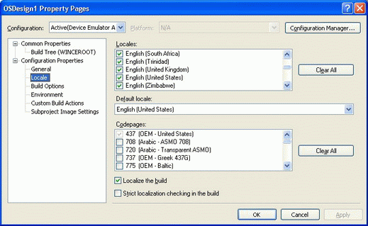
Figure 1-2 Locale property page
The Locale property page enables you to configure the following options for the run-time image:
¦Locales Selects the languages that will be available to localize the run-time image. If a selected language has a default ANSI and OEM code page, the code page is automatically added to the OS design, as indicated by a marked corresponding code page entry in the Codepages list