short text descriptions that appear in little yellow boxes when you pause the cursor over a toolbar button. A longer description of the icon’s function appears in the status bar at the bottom of the screen.
The
? Coordinates of the cursor: The
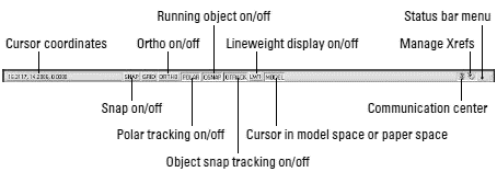
Figure 2-4: Status (bar) check.
 If the coordinates in the lower-left corner of the screen are grayed out, then coordinate tracking is turned off. Click the coordinates so that they appear in dark lettering that changes when you move the cursor in the drawing area.
? SNAP, GRID, and ORTHO mode buttons:
These three buttons control three of AutoCAD’s tools for ensuring precision drawing and editing:
• Snap constrains the cursor to regularly spaced hot spots, enabling you to draw objects a fixed distance apart more easily.
• Grid displays a series of regularly spaced dots, which serve as a distance reference.
• Ortho constrains the cursor to horizontal and vertical relative movement, which makes drawing orthogonal (straight horizontal and vertical) lines easy.
See Chapter 3 for instructions on how to configure these modes and Chapter 4 for information about why, when, and how to use them in actual drawing operations.
? POLAR tracking mode button: Polar tracking causes the cursor to prefer certain angles when you draw and edit objects. By default, the preferred angles are multiples of 90 degrees, but you can specify other angle increments, such as 45 or 30 degrees. See Chapter 4 for instructions to specify the polar tracking angles that you prefer. Clicking the POLAR button toggles polar tracking on or off. Ortho and polar tracking are mutually exclusive — turning on one mode disables the other.
? Running Object Snap (OSNAP) and Object Snap Tracking (OTRACK) buttons:
• When you turn on
• When you turn on
AutoCAD LT doesn’t include the object snap tracking feature, so you won’t see an OTRACK button on its status bar.
? Lineweight (LWT) display mode button: One of the properties that you can assign to objects in AutoCAD is
? MODEL/PAPER space button: As I describe in the section “Main course: The drawing area” later in this chapter, the drawing area is composed of overlapping tabbed areas labeled Model, Layout1, and Layout2 by default. The Model tab displays a part of the drawing called
• When the MODEL/PAPER button says MODEL, drawing and editing operations take place in model space, inside a viewport.
• When the button says PAPER, drawing and editing operations take place in paper space on the current layout.
Don’t worry if you find model space and paper space a little disorienting at first. The paper space layout setup information in Chapter 3 and plotting instructions in Chapter 12 will help you get your bearings and navigate with confidence.
 ? Maximize/Minimize Viewport button (paper space layouts only): When you’re looking at one of the Layout tabs instead of the Model tab, the status bar displays an additional Maximize Viewport button. Click this button to expand the current paper space viewport so that it fills the entire drawing area. Click the button — now called Minimize Viewport — again to restore the viewport to its normal size. (Chapter 3 describes viewports.)
? Communication Center: This button opens a dialog box containing recent AutoCAD- related headlines that Autodesk thinks you may find useful. The headlines are grouped into categories called
? Manage Xrefs: You won’t see this combination button and notification symbol until you open a drawing that contains xrefs (external DWG files that are incorporated into the current drawing). Chapter 13 tells you how to use xrefs and what the Manage Xrefs button does.
? Status Bar Menu: When you click the easy-to-miss downward-pointing arrow near the right edge of the status bar, you open a menu with options for toggling off or on each status bar button. Now you can decorate your status bar to your taste.
You can open dialog boxes for configuring many of the status bar button functions by right-clicking the status bar button and choosing Settings. Chapters 3 and 4 give you specific guidance about when and how to change these settings.
A button’s appearance shows whether the setting is turned on or off. Depressed, or down, means on; raised, or up, means off. If you’re unclear whether a setting is on or off, click its button; its mode will change and the new setting will be reflected on the command line — Osnap off, for example. Click again to restore the previous setting.
If the title bars, menu bar, and status bar are the Windows equivalent of comfort food — familiar, nourishing, and unthreatening — then the command line area, shown in Figure 2-5, must be the steak tartare or blood sausage of the AutoCAD screen feast. It looks weird, turns the stomachs of newcomers, and delights AutoCAD aficionados. The hard truth is that you have to come to like — or at least tolerate — the command line if you want to become at all comfortable using AutoCAD.

Figure 2-5: Obey the command line.
You need to get up close and personal with the command line for four reasons: