The main function of the linker is to combine multiple object files into a larger relocatable object file, a shared object file, or a final executable image. In a typical program, a section of code in one source file can reference variables defined in another source file. A function in one source file can call a function in another source file. The global variables and non-static functions are commonly referred to as
The compiler creates a symbol table containing the symbol name to address mappings as part of the object file it produces. When creating relocatable output, the compiler generates the address that, for each symbol, is relative to the file being compiled. Consequently, these addresses are generated with respect to offset 0. The symbol table contains the global symbols defined in the file being compiled, as well as the external symbols referenced in the file that the linker needs to resolve. The linking process performed by the linker involves symbol resolution and symbol relocation.
Figure 2.3 illustrates these two concepts in a simplified view and serves as an example for the following discussions.
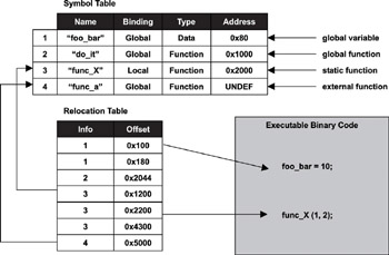
Figure 2.3: Relationship between the symbol table and the relocation table.
For an executable image, all external symbols must be resolved so that each symbol has an absolute memory address because an executable image is ready for execution. The exception to this rule is that those symbols defined in shared libraries may still contain relative addresses, which are resolved at runtime (dynamic linking).
A relocatable object file may contain unresolved external symbols. Similar to a library, a linker-reproduced relocatable object file is a concatenation of multiple object files with one main difference-the file is partially resolved and is used for further linking with other object files to create an executable image or a shared object file. A shared object file has dual purposes. It can be used to link with other shared object files or relocatable object modules, or it can be used as an executable image with dynamic linking.
2.3 Executable and Linking Format
Typically an object file contains
· general information about the object file, such as file size, binary code and data size, and source file name from which it was created,
· machine-architecture-specific binary instructions and data
· symbol table and the symbol relocation table, and
· debug information, which the debugger uses.
The manner in which this information is organized in the object file is the
This interoperability means a developer can choose a compiler from vendor A to produce object code used to form a final executable image by a linker from vendor B. This concept gives the end developer great flexibility in choice for development tools because the developer can select a tool based on its functional strength rather than its vendor.
Two common object file formats are the common object file format (COFF) and the executable and linking format (ELF). These file formats are incompatible with each other; therefore, be sure to select the tools, including the debugger, that recognize the format chosen for development.
We focus our discussion on ELF because it supersedes COFF. Understanding the object file format allows the embedded developer to map an executable image into the target embedded system for static storage, as well as for runtime loading and execution. To do so, we need to discuss the specifics of ELF, as well as how it relates to the linker.
Using the ELF object file format, the compiler organizes the compiled program into various system-defined, as well as user-defined, content groupings called
A section also contains important information such as the load address and the run address. The concept of load address versus run address is important because the run address and the load address can be different in embedded systems. This knowledge can also be helpful in understanding embedded system loader and link loader concepts introduced in Chapter 3.
Chapter 1 discusses the idea that embedded systems typically have some form of ROM for non-volatile storage and that the software for an embedded system can be stored in ROM. Modifiable data must reside in RAM. Programs that require fast execution speed also execute out of RAM. Commonly therefore, a small program in ROM, called a
The ELF file format has two different interpretations, as shown in Figure 2.4. The linker interprets the file as a linkable module described by the section header table, while the loader interprets the file as an executable module described by the program header table.
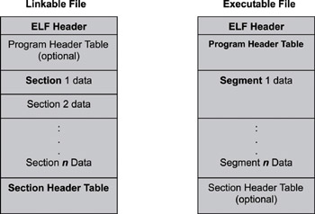
Figure 2.4: Executable and linking format.
Listing 2.1 shows both the section header and the program header, as represented in C programming structures. We describe the relevant fields during the course of this discussion.
Listing 2.1: Section header and program header.
typedef struct {
Elf32_Word sh_name;
Elf32_Word sh_type;
Elf32_Word sh_flags;